Built with: Java, WPILib (FRC library)
Demo
Features Overview
- Conversion from input speed into swerve module states
- Automatic robot heading and speed correction with Limelight and AprilTag
- Custom drivetrain PID controller
- Turret
Table of Contents
- Introduction to Swerve Drive
- Swerve Drive Module
- Explanation of Code Structure
- Getting Joystick Input
- Limelight & Limelight Math
- Strafe to Point Command
- Custom PID Controller
Introduction to Swerve Drive
Swerve drive is a type of omnidirectional (all-directions) drivetrain that independently controls the steering and driving of each wheel. This is contrary to tank drive, which only moves forward/backward and turn at a time.
The summarized process of swerve drive is as follows:
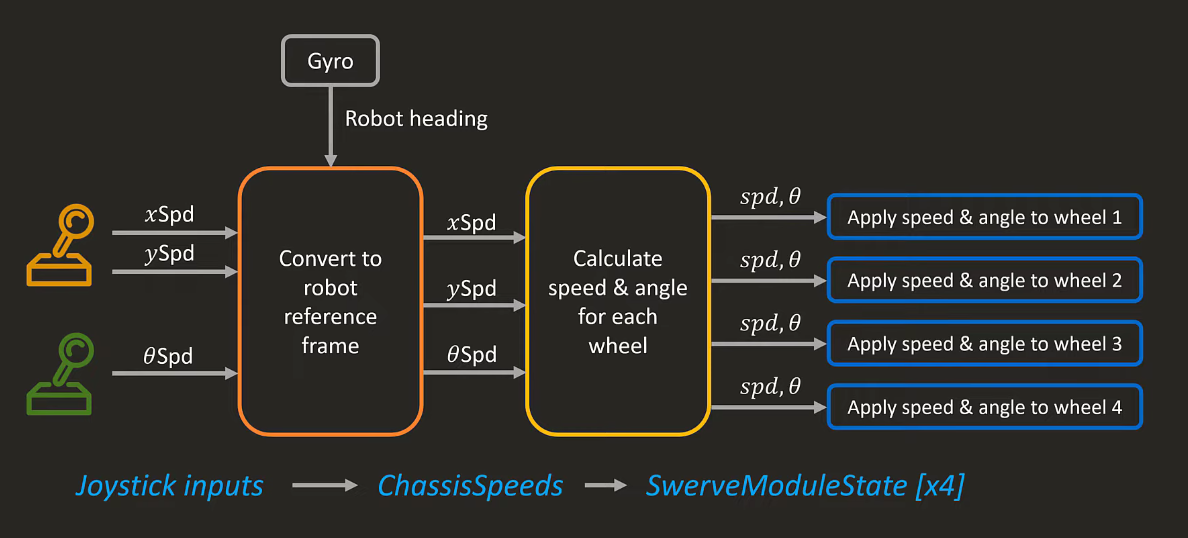
The first step is sending inputs with a joystick to our robot, just like what we normally do to control a character in a game. The joystic input is converted into a chassis speed in robot's reference frame. From this, each wheel's speed and angle are calculated and packaged as a swerve module state. These states are then applied to the corresponding swerve modules.
Conventionally, in a controller, the left stick is used for driving and the right stick is for steering.
Swerve Drive Modules
There are two different types of swerve modules: coaxial and differential modules:
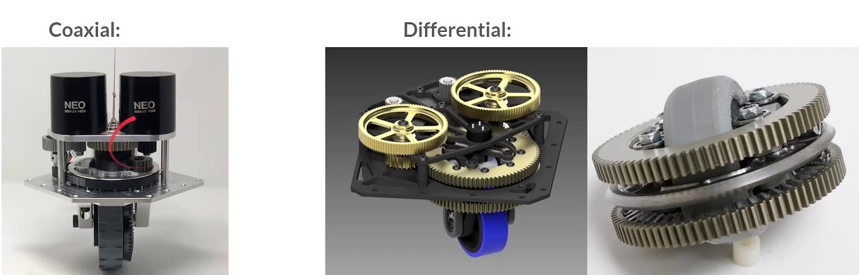
The main difference lies in how each module controls steering and driving. A coaxial module has a drive and steer motors separate, so it controls driving and steering independently. On the other hand, a differential motor has two drive motors and uses their opposing rotation to create translation and the rotation in the same direction.
Most FRC teams use coaxial swerve modules because the independent drive and steer motors allow for separate PID tuning for driving and steering. In my swerve driving chassis, I use a coaxial MK4 swerve module.
Explanation of Code Structure
There are two subsystems in my robot chassis: swerve and turret. The swerve subsystem is responsible for driving, and the turret subsystem controls the chassis-mounted camera.
Most FRC robots, including my robot chassis, are command-based robots. Commands are important during matches for running tasks like resetting robot heading, driving, as well as subsystem-specific tasks. Commands are activated in response to controller inputs or system conditions (e.g. Triggers).
Primary Files & Their Roles
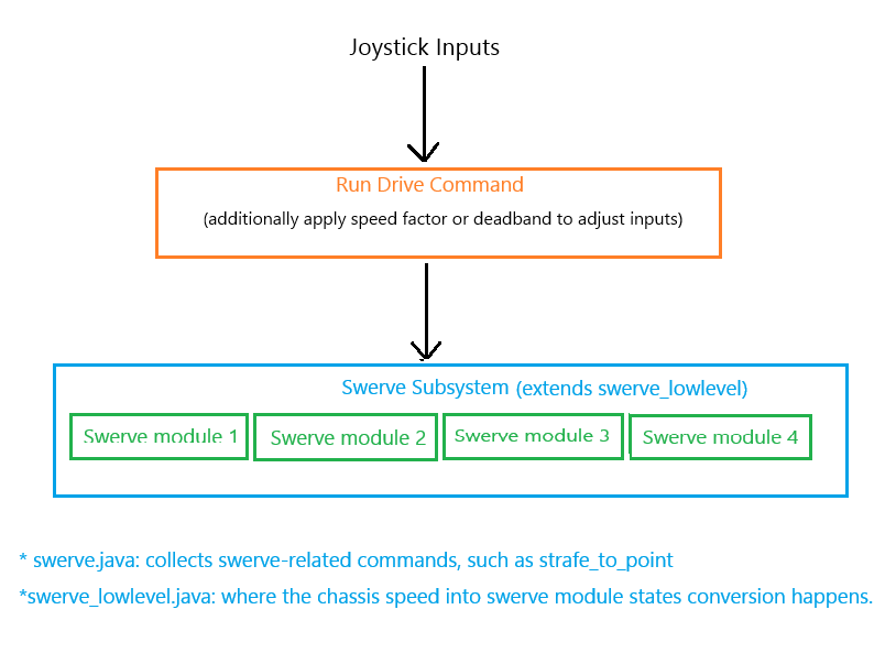
- swerve.java: Contains test commands like strafing to an AprilTag by integrating Limelight vision. Extends swerve_lowlevel.java that converts chassis speeds into module states and updates module outputs.
- turret.java: Controls the camera mounted on the chassis. Rotates to scan for AprilTags and triggers related commands (e.g. from swerve.java) based on detection conditions.
- command.java: Includes the main drive command used during the teleop mode.
- bindings.java: Maps controller buttons to specific robot commands, including the drive command.
- oi.java: Defines the controller instance and applies custom input processing like deadband and shaping functions.
- config.java: Stores PID configurations for motor control tuning.
- constants.java: Stores static values like motor IDs, gear ratios, and other key hardware parameters.
Processing Joystick Inputs
The first step toward driving is sending inputs with a joystick to tell a robot in which direction it should drive at what speed. The input coming from the left stick is x and y speeds used for driving. Note that in FRC, x-axis is vertical and y-axis is horizontal. The input coming from the right stick is an omega speed, which is the steering speed.
Drive Command Implementation
//In commands.java
public static Command teleop_swerve_drive(robot robot, Supplier<Translation2d> drive_func, Supplier<Double> steer_func) {
    final double drive_speed_factor = 2;
    final double steer_speed_factor = 1.5;
    return robot.swerve.strafe_field_relative(() -> {
        return ChassisSpeeds.fromFieldRelativeSpeeds(new ChassisSpeeds(
            drive_func.get().getX() * drive_speed_factor,
            drive_func.get().getY() * drive_speed_factor,
            steer_func.get() * steer_speed_factor
        ), robot.swerve.get_heading());
    });
}
I send the joystick inputs as a field-relative chassis speeds to make robot drive in a consistent direction relative to the game field, not its own orientation. I additionally use speed factors to amplify input speeds.
Setting a Default Command for the Swerve Subsystem
The teleop drive command is set as the default command for the swerve subsystem, so that it expects to drive by default:
//In bindings.java
Supplier<Translation2d> ctrl_drive = () -> oi.vector_deadband(oi.get_left_stick(oi.drive), oi::shape);
Supplier<Double> ctrl_steer = () -> oi.deadband_precise(-oi.drive.getRightX(), oi::shape);
robot.swerve_subsystem.setDefaultCommand(commands.teleop_swerve_drive(robot, ctrl_drive, ctrl_steer));
When passing joystick inputs to a command, they must be sent with a Supplier to continuously send updated values as the command runs. Without using a Supplier, the command would receive only a single, fixed input captured at the beginning. This is a Java-specific problem.
I also refine the inputs by using deadbanding and shaping functions:
- Deadbanding eliminates minor stick movements and minimizes robot drifting and jittering with small input changes.
- Shaping function transforms the input curve. My shaping function combines exponential and quadratic fuctions to create a snappy movement and scale the input smoothly as it increases. I created my shaping function easily by visualizing it via Demos.
Converting Chassis Speeds into Module States
The chassis speeds are then sent to each swerve modules as SwerveModuleState:
//In swerve_lowlevel.java
//This is done in periodic()
SwerveModuleStates[] module_states = constants.swerve.drive_kinematics.toSwerveModuleStates(desired_chassis_speeds);
modules[0].set_desired_state(module_states[0]);
modules[1].set_desired_state(module_states[1]);
modules[2].set_desired_state(module_states[2]);
modules[3].set_desired_state(module_states[3]);
A SwerveModuleState object contains information about the velocity and angle of a singular module. The SwerveDriveKinematics class converts between a chassis speeds and several module states.
SwerveDriveKinematics Initialization
A SwerveDriveKinematics object is created for a single robot chassis, initialized with the distance of each swerve module relative to the center of the robot:
//In constants.java

//The horizontal distance from a wheel to the robot center
public static final double half_wheel_base_meters = 0.52705 / 2;

public static final Translation2d[] mount_positions = {
    new Translation2d(half_wheel_base_meters, half_wheel_base_meters), //front-left
    new Translation2d(half_wheel_base_meters, -half_wheel_base_meters), //front-right
    new Translation2d(-half_wheel_base_meters, half_wheel_base_meters), //back-left
    new Translation2d(-half_wheel_base_meters, -half_wheel_base_meters) //back-right
};

public static final SwerveDriveKinematics drive_kinematics = new SwerveDriveKinematics(
    mount_positions[0], mount_positions[1], mount_positions[2], mount_positions[3]
);
Converting a Module State into Motor Outputs
A module processes a desired state like this:
public void set_desired_state(SwerveModuleState state) {
    state.optimize(desired_state.angle); //optimize angle from the previous state
    desired_state = state;
    drive_motor.setControl(new VelocityVoltage(Units.radiansToRotations(state.speedMetersPerSecond / constants.swerve.wheel_radius)));
    steer_motor.setControl(new PositionVoltage(state.angle.getRotations()));
}
First, the incoming heading angle is optimized based on the previous robot heading. This optimization minimizes the required rotation of the wheel by potentially reversing the direction the wheel spins, adjusting the angle by 180 degrees. When used with a PID controller's continuous input functionality, the largest angle a wheel would ever rotate is 90 degrees. This significantly reduces the time needed for the wheel to reach the desired orientation.
For instace, suppose the wheel's current angle is 10°, and it wishes to rotate to 200°. Instead of rotating by 190°, the wheel can travel a shorter distace by rotating to 200° - 180° = 20°.
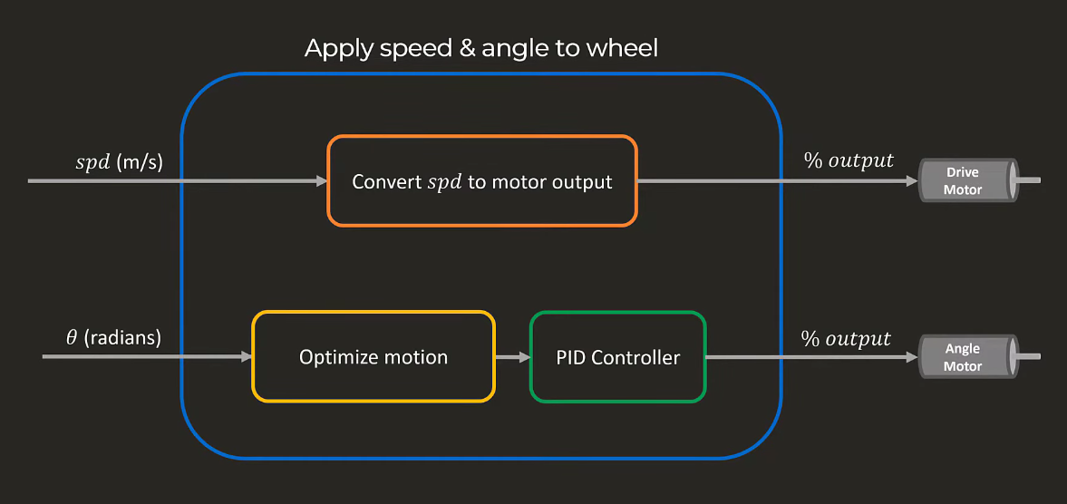
After the angle optimization, the motors' voltage outputs are set with the desired state.
Normally, motor output is calculated using a PID controller that adjusts output based on the current error (the difference in current value to the target value), PID constants, and system constraints like maximum velocity. However, this is not displayed in the code because I use TalonFX motors which handle PID control internally. The PID configuration is set up within each motor's own configuration (in config.java).
This is the summarized workflow of converting module states into motor outputs:
AprilTag Localization with Limelight Vision
In the video demo, the robot chassis accelerates until it is a certain distance away from the AprilTag. The robot detects an AprilTag with the Limelight camera mounted on the chassis.
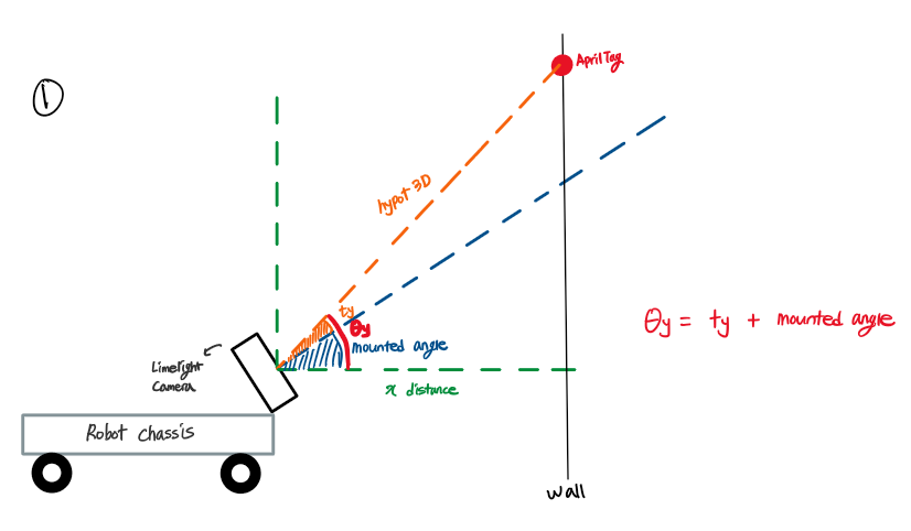
Limelight provides several helper functions that locates a tag's position in 3D space. With those helper functions, I calculate the x and y distances the robot has to move to reach the detected tag:
public static Translation2d tag_translation2d(LL ll, double extra_tx) {
if (!LimelightHelpers.getTV(ll.name)) { //check is limelight sees a tag
return new Translation2d();
}
Pose3d tag = LimelightHelpers.getTargetPose3d_CameraSpace(ll.name); //tag's 3D position
double theta_y = LimelightHelpers.getTY(ll.name) + ll.mount_angle.getDegrees();
double theta_x = LimelightHelpers.getTX(ll.name) + extra_tx;
double hypot_3d = tag.getTranslation().getNorm();
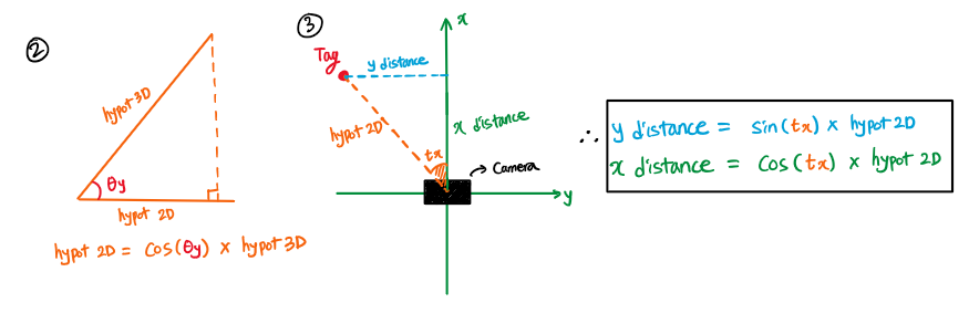
double hypot_2d = Math.cos(Units.degreesToRadians(theta_y)) * hypot_3d;
double x_dist = Math.cos(Units.degreesToRadians(theta_x)) * hypot_2d;
double y_dist = Math.sin(Units.degreesToRadians(theta_x)) * hypot_2d;
return new Translation2d(x_dist, y_dist);
}Let me explain the math visually:
Strafing to an AprilTag Command
//In swerve.java
public Command strafe_to_tag(LL limelight) {
    //minimum hypotenous lengnth to stop robot (kind of deadband)
    final double hypot_tolerance = Units.inchesToMeters(1.5);
    //ensures the robot always stops 1.7m away from a tag
    final double set_distance = 1.7;
    Debouncer debouncer = new Debouncer(0.01);
    Debouncer debouncer_tv = new Debouncer(0.2, DebounceType.kFalling);
    Object obj = new Object() {
        Translation2d offset;
    };

    return Commands.runOnce(() -> {
        //resets the PID controller for x speed
        x_pid.reset();
    }, swerve_subsystem)
    .andThen(set_desired_chassis_speeds(() -> {
        double x_speed = 0.5, y_speed = 0; //minimum speed

        if(LimelightHelpers.getTV(limelight.name)) { //if limelight sees a tag
            //calculates the x and y distance to the tag
            obj.offset = math_utils.tag_translation2d(limelight, -get_heading().getDegrees());
        }

        //if limelight still sees a tag within the specified time
        if (debouncer_tv.calculate(LimelightHelpers.getTV(limelight.name))) {
            // Calculate distance error from initial tag position
            Translation2d err = new Translation2d(set_distance - obj.offset.getX(), obj.offset.getY());
            double err_len = err.getNorm();

            //calculates the required x speed to reach the tag, with PID
            double speed = x_pid.calculate(err_len);

            //normalizes the error vector to get a unit direction vector.
            //then multiply the scalar speed from PID.
            double output = err.div(err_len == 0 ? 1 : err_len).times(speed);
            x_speed = output.getX();
            y_speed = output.getY();

            //deadbanding 1
            if (debouncer.calculate(err_len < hypot_tolerance)) {
                //if the error length exceeds the hypotenus tolerance, stops moving
                x_speed = 0;
                y_speed = 0;
            }
        }

        //deadbanding 2
        if (!is_theta_within(20)) { //custom PID deadbanding for steering
            //if the steering angle change is within 20 degrees, stop
            x_speed = 0;
            y_speed = 0;
        }

        return new ChassisSpeeds.fromRobotRelativeSpeeds(x_speed, y_speed, get_heading());
    }));
}