Built with: C++, ROS2, SolidWorks, Altium
Overview
I designed and built a modular swerve-drive robotic platform demonstrating mechanical design, structural analysis, and integrated hardware/software system. The system is built on a compact 15 × 15-inch chassis and includes a swerve-drive mobility system with an auxiliary vacuuming feature.
Software
I developed a custom ROS 2 controller to implement swerve-drive kinematics and control logic, validating system behavior through RViz simulation by publishing odometry and TF transforms. In parallel, I prototyped and simulated LiDAR-based SLAM and A* path planning within a Gazebo environment, maintaining a separate Git repository for easier debugging and development.
I am currently exploring efficient approaches to coverage path planning. The A* search planner was to establish a starting point, and I am building on it toward full-coverage solutions.
Below is a demo video showcasing the integrated LiDAR SLAM mapping and A* path planning in action:
Hardware
Electronics
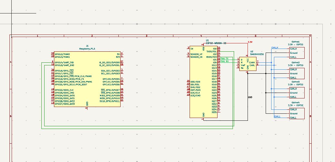
I designed modular power distribution and control electronics in Altium, integrating power, motor drivers, sensors, and microcontrollers. The wiring layout was structured for easy upgrades while ensuring reliable operation during high-speed omnidirectional motion.
Hardware Components
The system includes:
- 8 x N5065S 270kV BLDC motor
- 8 x V5 80A ESC 3-6S
- 1 x MPU-6050 IMU
- 1 x battery
- 1 x Rasberry Pi 5
- 1 x Esp32
I used two microcontrollers to manage different levels of control:
- Raspberry Pi 5 to handle higher-level logic, including mapping, localization, and coverage path planning.
- ESP32 to run low-level control tasks such as PID loops, motion profiling, and swerve-drive kinematics.
The IMU provides gyroscope data, which I use to obtain an accurate robot heading for updating odometry and localization.
CAD & Mechanical Design
Coaxial Swerve Module CAD Design
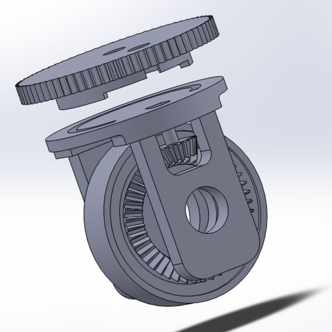
Both the drive and steering mechanisms are two-stage systems. The drive uses bevel and spur gears for compact torque transmission and precise high-speed motion, while the steering uses spur and belt gears to provide smooth, low-backlash rotation.
I manually designed the gears and derived mathematical equations to calculate the required dimensions and gear ratios for reliable motion transfer, referencing this website.
Gear Ratios and Drive Speed Calculations
The brushless motor can reach up to 6,480 RPM at 24 V. Gear reduction was applied to achieve the desired drive speed:
Wheel radius: r = 1.5 in
Wheel circumference: C = 2 * pi * r ≈ 9.425 in
Drive free speed:
v_wheel_free = (N_motor * C) / 60
= (6480 * 9.425) / 60 ≈ 1017.9 in/s ≈ 25.86 m/s
Drive speed after gear reduction:
v_drive = v_wheel_free / (Stage1_ratio * Stage2_ratio)
= 25.86 / (1.7 * 3) ≈ 5.07 m/s
As a result, the robot can drive up to 5.07 m/s (no-load).
Finite Element Analyis (FEA)
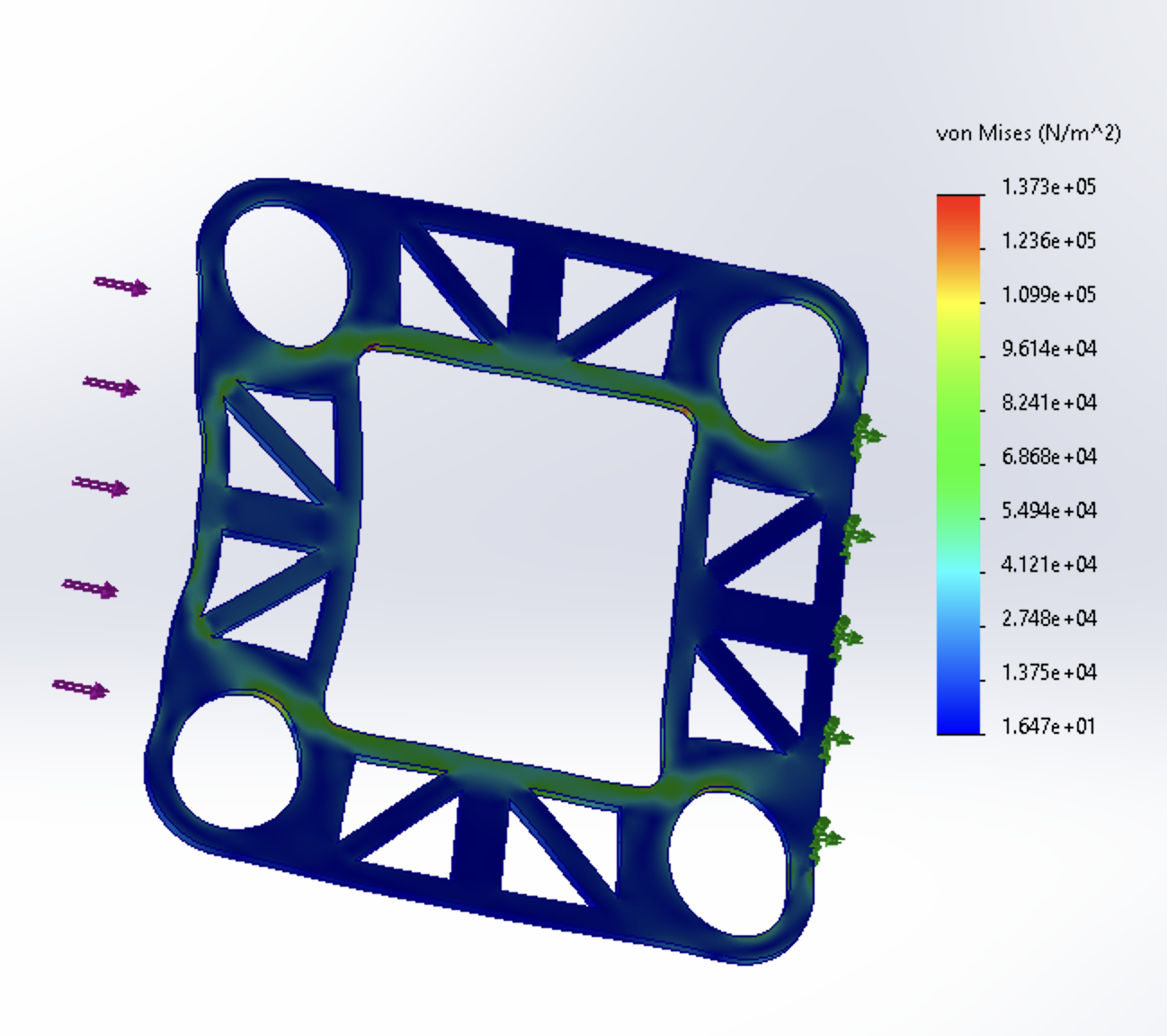
I used FEA to validate load paths and ensure the frame could withstand operational forces. SolidWorks Simulation identified major structural issues early, while higher-accuracy simulations in ANSYS evaluated precise stress distributions and impact loading during crash scenarios.
Completed Final Assembly
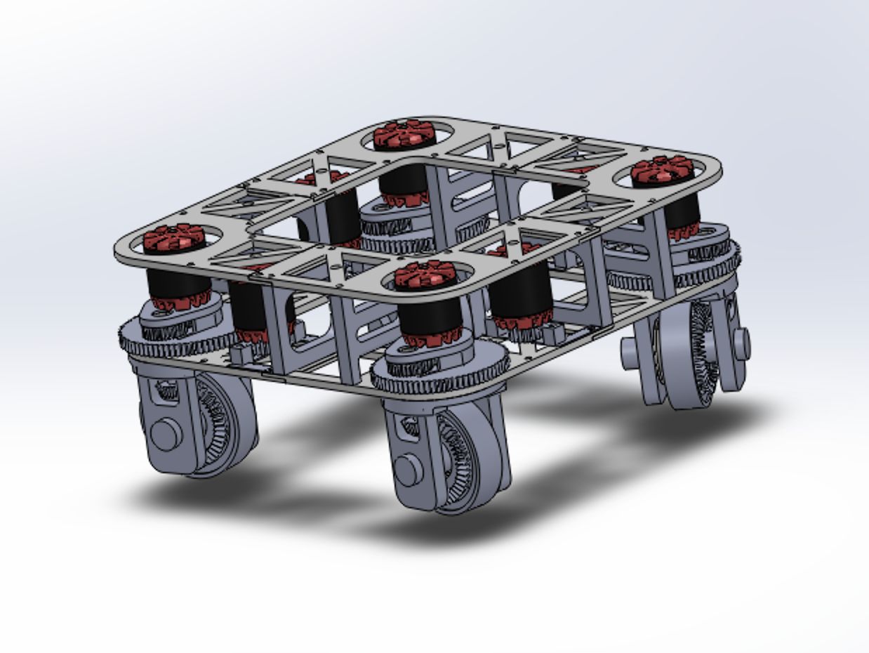
The final frame integrates all modules with optimized stiffness and minimal weight. The chassis is designed to support future upgrades and to protect the electronics during collisions or high-load maneuvers.