Overview
A fixed-wing VTOL UAV I've been building since May. I'm currently in the aircraft CAD design and adjustment stage.
Project Roadmap & Progress
- [V] Determine requirements
- [V] Constraint analysis & choose design point
- [V] Airfoil selection & wing design
- [V] Fuselage design
- [V] Tail design
- [ ] SolidWorks CAD assembly (In Progress)
- [ ] Aerodynamics & FEA using Ansys Fluent
- [ ] Configure detailed hardware & order parts
- [ ] 3D print parts & assemble
- [ ] Fly my UAV! 🚀
Writing Aircraft Requirements
I selected the design from these requirements:
- Endurance: 40+ minutes (long-flight focus)
- Takeoff / landing: vertical — QuadPlane VTOL
- Weight: under 7 kg (targeting 4–5 kg)
- Stall speed: ~13 m/s
Constraint Analysis & Finding the Design Point
Before designing the actual aircraft, I needed a target: how big the wing should be and how much power the motor needs. I wrote a Python program that takes my starting estimates (aspect ratio, cruise speed, climb rate, etc.) and plots two diagrams:
- Thrust-to-Weight ratio (T/W) vs Wing Loading (W/S)
- Power-to-Weight ratio (P/W) vs Wing Loading (W/S)
Together they show the range of wing sizes and motor power that can actually meet my requirements. Picking a point inside that range gives me the design point, which becomes the foundation for the rest of the build.
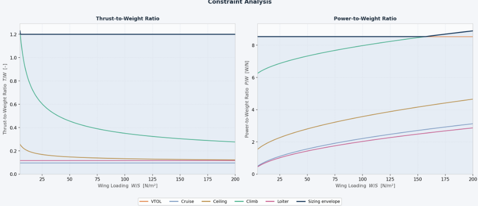
My selected design point is:
- Wing Loading: 60
- T/W: 1.18
- P/W: 8
Using the numbers above and my initial guesses, I can adjust my assumption more realistically:
- Total UAV mass: 4.76 kg
- Weight = 4.79 * 9.81 = 46.9899
- Total payload mass: 0.95 kg
- payload convergence error: 0.01
- Power required: 67 Watt
- Shaft power required: 104 Watt
- Safe stall speed: 13.70 m/s
- Safe turn speed: 14.52 m/s
These results may change as I go.
Airfoil Selection
I chose the SD7062 airfoil to achieve my goal of good endurance and long flight time. It's a high-lift airfoil popular on UAVs. It makes plenty of lift even at slow speeds, which keeps the stall speed low and helps carry payload over long flights.
XFLR5 Wing Design Tuning & Analysis
Starting from a baseline wing, I made three changes:
- Tapered wingtip: shifts lift toward an elliptical distribution, cutting induced drag.
- Twist (washout): tip set at a lower incidence so the root stalls first, keeping roll/aileron control near stall.
- Dihedral: adds roll stability.
I analyzed performance using the Horseshoe Vortex (VLM) method in XFLR5, comparing the baseline wing against my tuned wing.
Polar diagrams: default vs tuned wing:
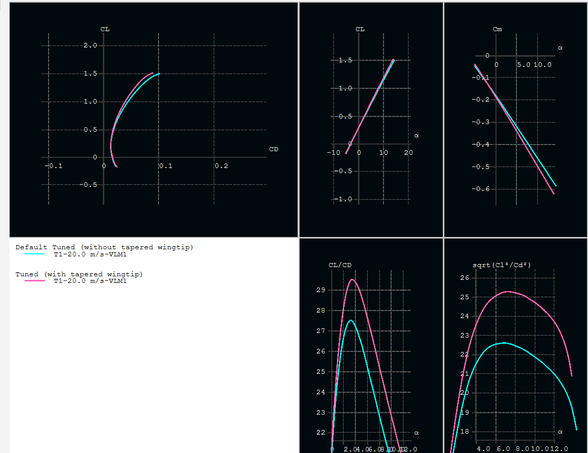
The graph above shows the performance different between the initial and tuned wing design. The tapered wingtip (pink) reaches a higher lift-to-drag ratio and a higher endurance factor than the default. It means less drag and longer flight time. And since the lift and stability curves stay almost the same, those gains come without any downside.
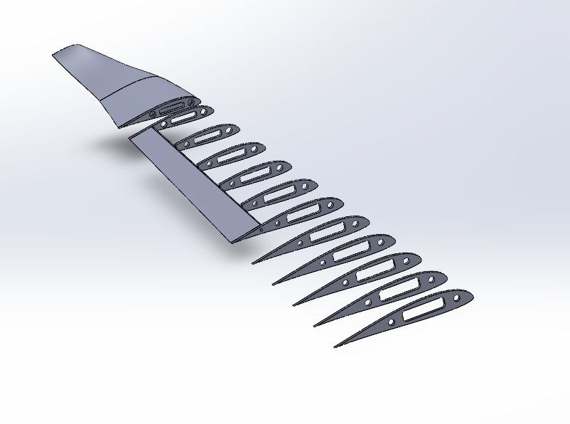
Wing Design:
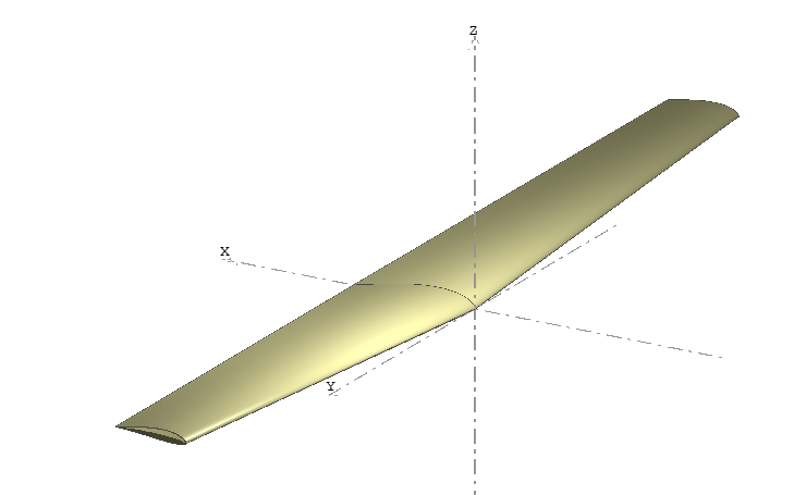
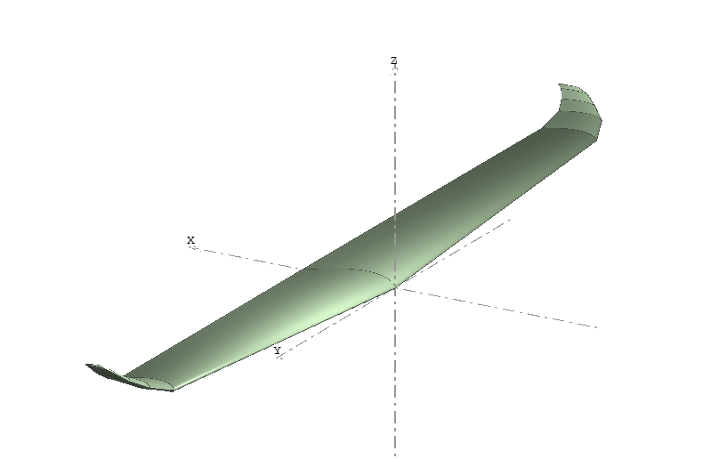
Left is the default design, and right is the final design I selected after several tuning.
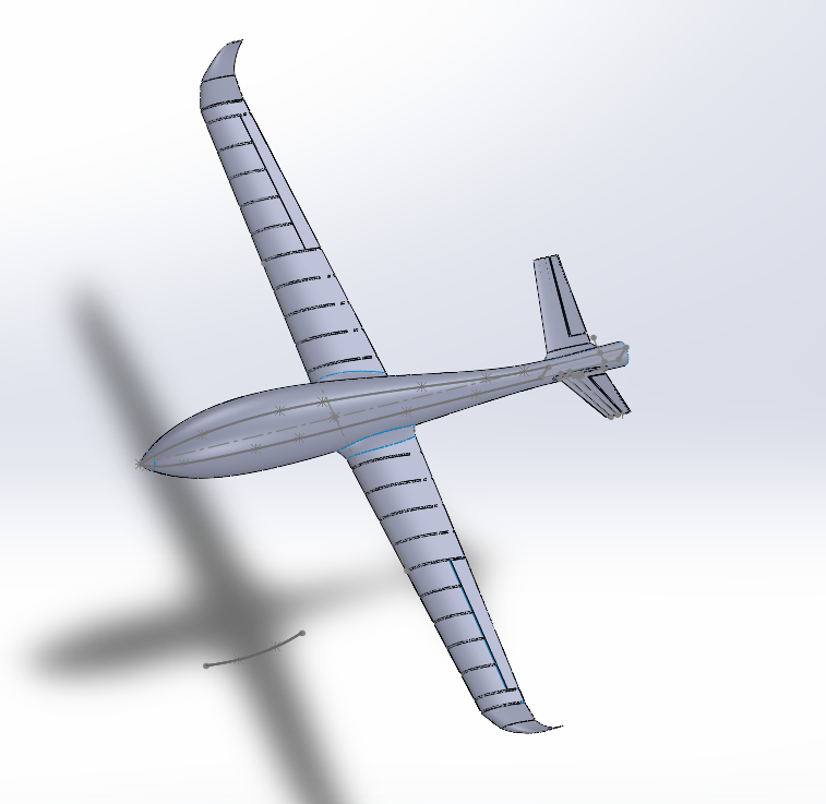
Aircraft CAD Design
Finalizing the wing design now, then moving on to hardware layout and the initial fuselage design.
Hardware List
These are my current estimates:
- Flight controller: Ardupilot
- rpi 5
- Battery
- 10 mm diameter carbon fiber rod (for wing body support)
- 4 mm diameter carbon fiber rod (for wing flap)
- ESCs x 5
- propeller x 5
- Servo motor for tilt rotor: 4
- Servo motor for wing flap: 2 x 2 = 4
- Servo for V tail: 2
- motor for rotors: 5
- Drone controller
- Control receiver
- FPV camera
- FPV transmitter
- antenna
- GPS
- airspeed sensor
- others