A 15 × 15 inch swerve robot built to explore mobile robotics control, navigation, and mechanical and electrical design.
- 5.07 m/s
- Max speed (no-load)
- 8
- Independently driven motors
- ROS 2
- Software framework
Robotics Software
Navigation: mapping, localization, and path planning
Built a ROS 2 navigation stack integrating LiDAR SLAM and A starpath planning. Published odometry and TF transforms to validate navigation behavior in Gazebo and Foxglove before deploying to hardware.
Swerve Drive Control
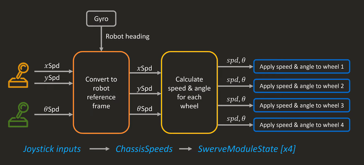
Developed a ROS-based swerve drive controller converting desired robot velocities into independent steering angles and wheel speeds for each module.
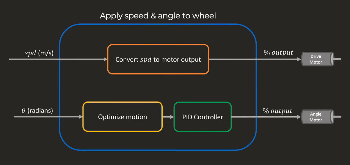
Implemented PID control and motion profiling for the drive and steering motors, with the low-level control loop running on the ESP32.
Testing swerve drive on a real robot:
Hardware
Electronics & Control Architecture
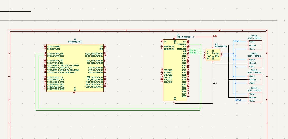
Designed the electronics architecture in KiCad, using modular power distribution and motor control for 8 BLDC motors through 80 A ESCs.
Separated high-level computation and real-time control across a Raspberry Pi 5 and ESP32. The Raspberry Pi handles navigation and mission planning, while the ESP32 handles time-sensitive motor control, PID loops, and swerve kinematics.
This separation prevents computationally expensive navigation tasks from interfering with the motor control loop.
Mechanical Design
Swerve Module
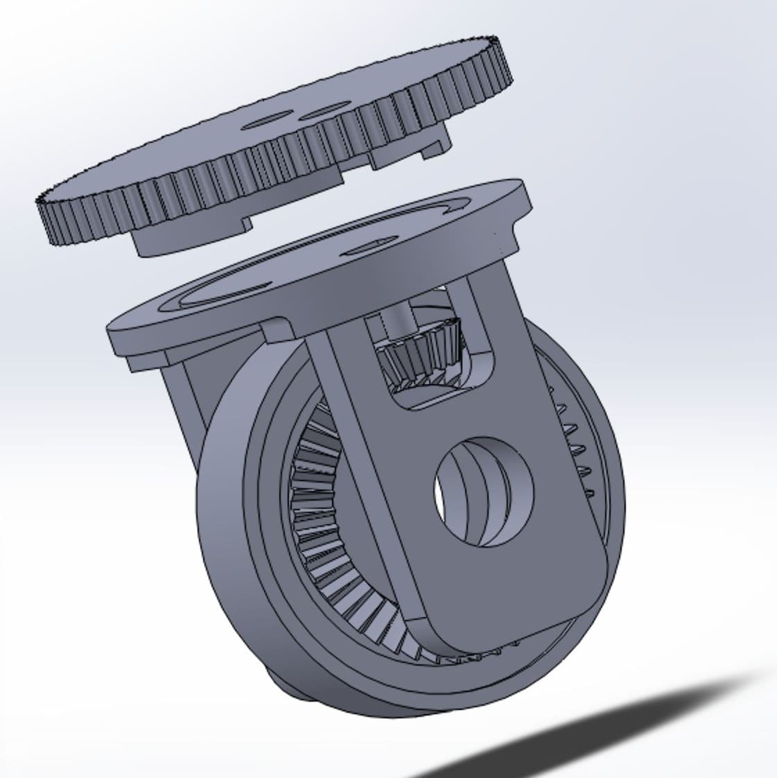
Designed the swerve drivetrain in SolidWorks with a two-stage drive system using bevel and spur gears for propulsion and a belt drive for steering.
Derived the gear ratios to achieve 5.07 m/s no-load speed while maintaining torque headroom for carpet and threshold traversal.
Structural Analysis
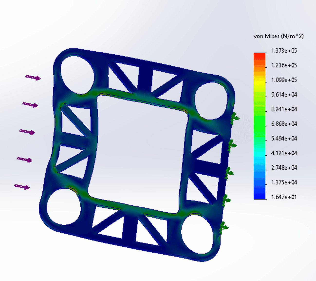
Used SolidWorks Simulation during the design process to identify structural issues, then used ANSYS for detailed stress distribution and impact-load analysis.
Final Frame Assembly
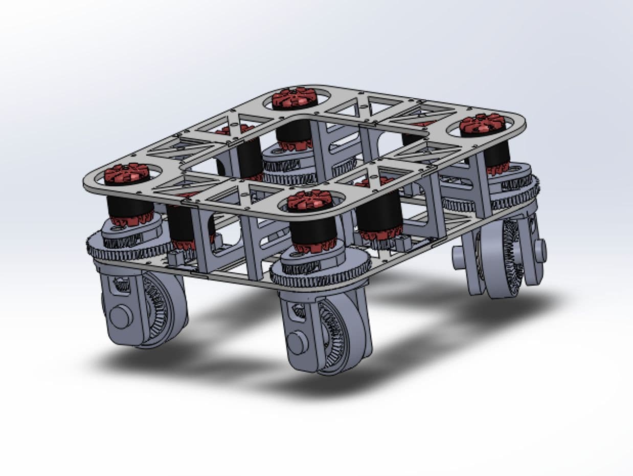
Integrated the mechanical, electrical, and computing systems into a compact frame designed to balance stiffness, weight, and component protection.
The modular frame and electronics layout leave room for future hardware and software upgrades without redesigning the entire platform.
Stack
- C++
- ROS 2
- Gazebo
- SolidWorks
- KiCad
- ESP32
- Raspberry 5