A fixed-wing VTOL UAV designed around aerodynamic and propulsion requirements, targeting 45 minutes of endurance while retaining vertical takeoff and landing capability.
- 45 min
- Endurance target
- 1.27 kg
- Design mass
- 7.0 m/s
- Stall speed
Preliminary Design
UAV Early-Design App
Built UAV Early Design to turn the flight requirements into a wing size, motor power and battery: a Python desktop app (PySide6 + Matplotlib) for the conceptual design of small battery-electric fixed-wing and VTOL UAVs, including quadplanes, tilt-rotor quadplanes and tiltrotors.
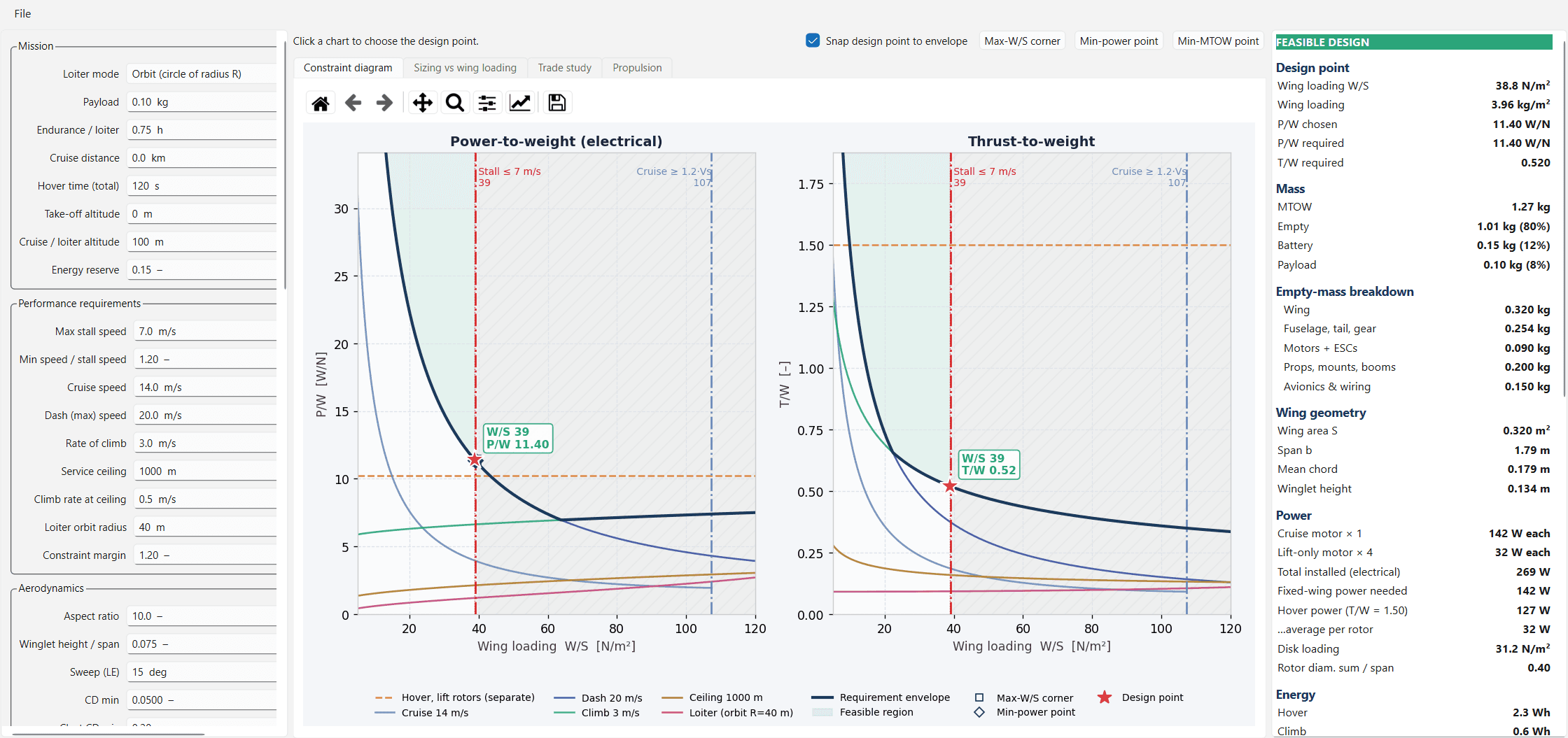
The app works in four stages:
- Constraint diagram: every requirement (hover, climb, service ceiling, cruise, dash speed, loiter and stall speed) is turned into the power-to-weight and thrust-to-weight it demands at each wing loading. The region that satisfies all of them is shaded, and clicking the chart picks the design point.
- Sizing: for the chosen design point, the app finds the take-off mass at which empty mass, battery and payload add up. Empty mass is built from components (wing, fuselage, motors, propellers, avionics), and the battery is sized from the energy of each mission leg.
- Trade studies: any requirement can be swept over a range to see how it changes the take-off mass, battery, installed power and wingspan.
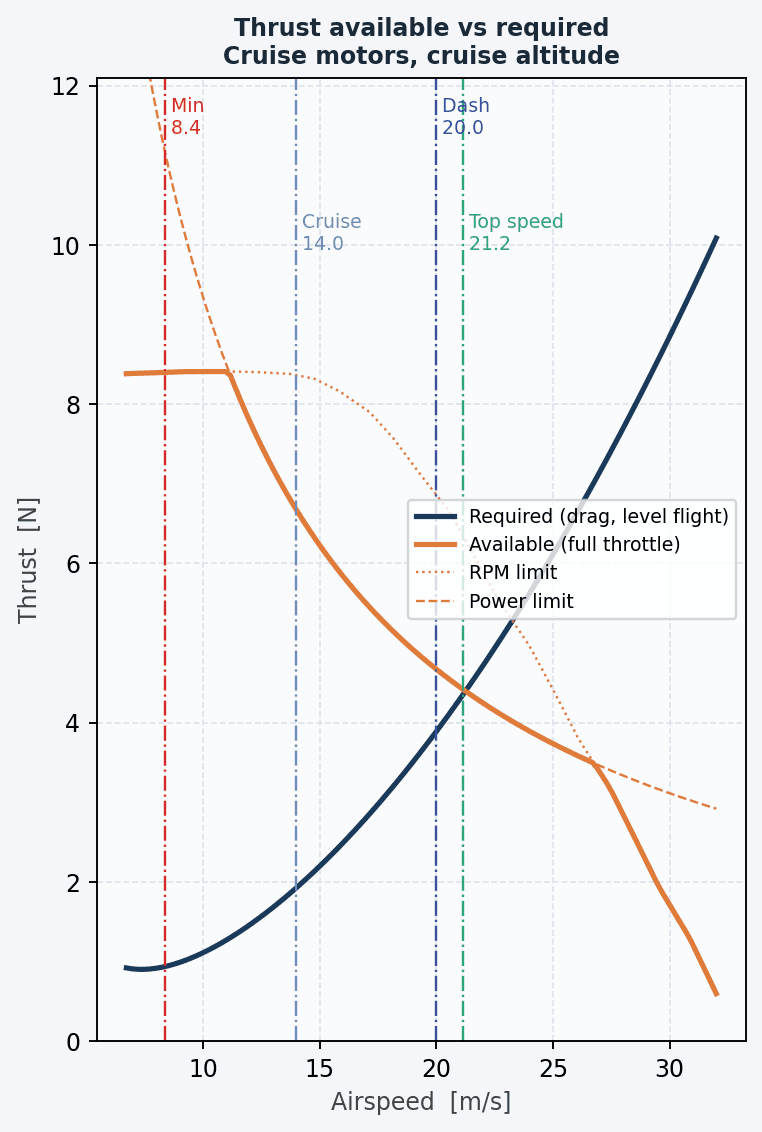
- Propulsion matching: propellers are selected from wind-tunnel data (UIUC Propeller Data Site) and APC performance data. For each flight condition the app gives RPM, efficiency, power, torque and current, and suggests motor Kv and battery capacity.
The aerodynamic, performance and hover models follow standard aircraft and rotorcraft design methods (Raymer, Aircraft Design: A Conceptual Approach; Leishman, Principles of Helicopter Aerodynamics). One design point was recalculated by hand in a separate script to verify the app's results.
Selecting the Design Point
The mission requirements entered were a 0.1 kg payload, 45 minutes of loiter, 14 m/s cruise, 20 m/s dash, 1.5 thrust-to-weight on the lift rotors for hover control, and a 15 % energy reserve.
Trade studies then showed which requirements drive the aircraft most. Stall speed had the largest effect, because it limits how small the wing can be:
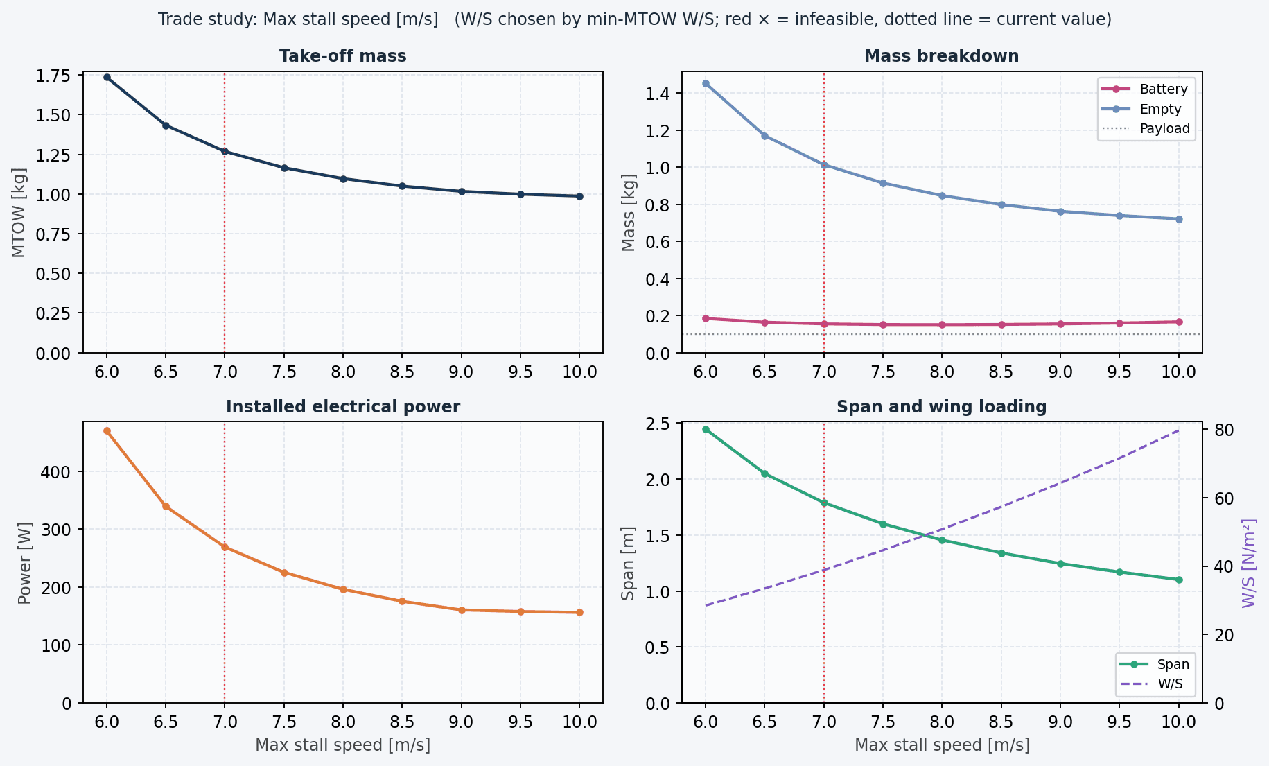
| Requirement | Take-off mass | Span |
|---|---|---|
| Stall ≤ 5 m/s | does not close | |
| Stall ≤ 6 m/s | 1.74 kg | 2.45 m |
| Stall ≤ 7 m/s | 1.27 kg | 1.79 m |
| Stall ≤ 8 m/s | 1.10 kg | 1.46 m |
| Endurance 45 → 60 min | 1.27 → 1.39 kg | |
| Dash speed 20 → 25 m/s | 1.27 → 1.41 kg |
The stall speed was set at 7 m/s. In the constraint diagram, the lightest aircraft sits right on the stall limit, so that point was selected as the design point:
Wing loading:            38.8 N/m²   (set by the 7 m/s stall limit)
Cruise-motor P/W:        11.4 W/N    (set by the 20 m/s dash)
Lift-rotor T/W:          1.50
Take-off mass:           1.27 kg
Wing:                    1.79 m span, 0.32 m² area, 0.18 m mean chord
Battery:                 3S 2100 mAh (23 Wh)
Propulsion Selection
The app ranked every propeller in its database by mission energy for each motor group. The selected propellers' measured efficiencies were fed back into the sizing, and the design converged in two iterations.
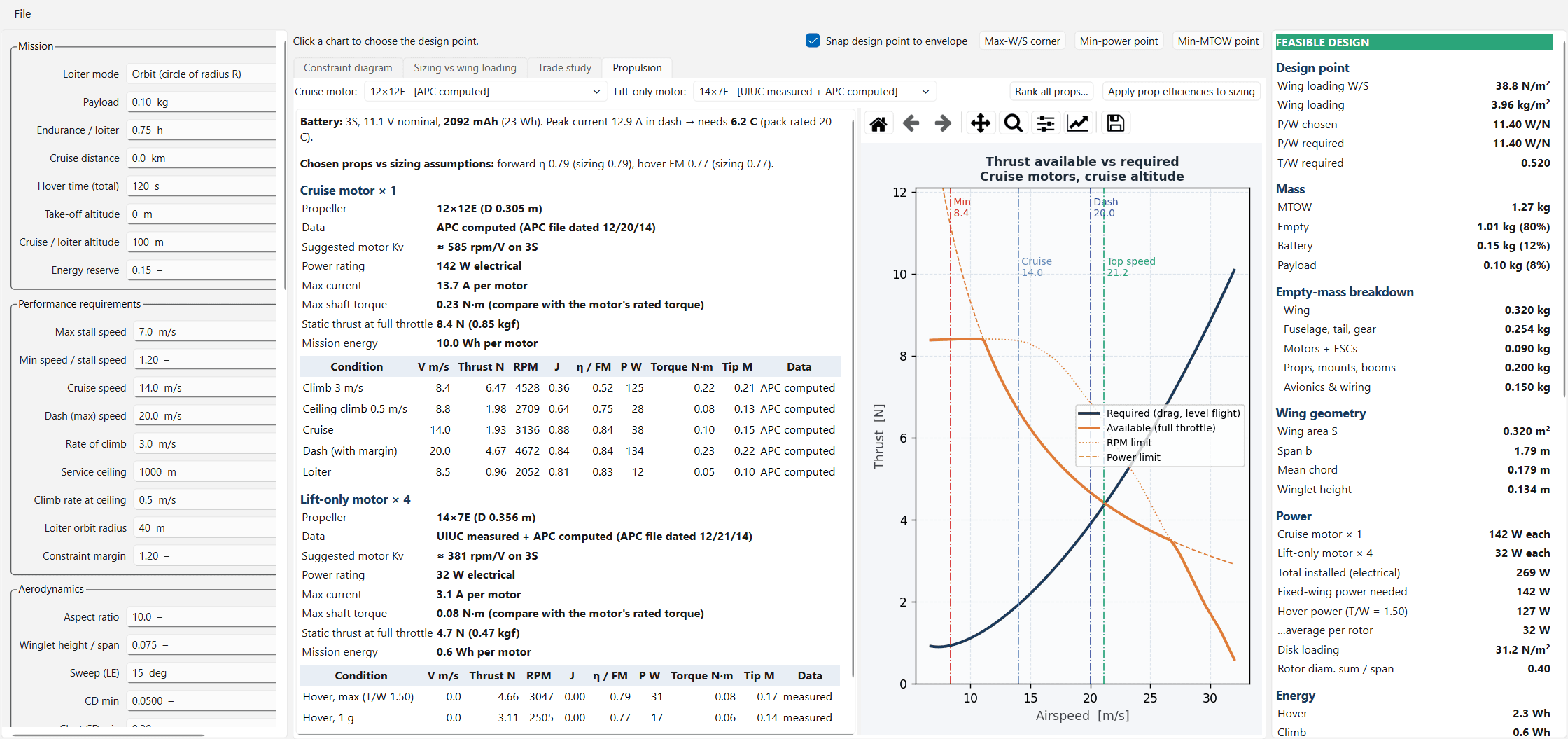
- Lift rotors: 4 × APC 14×7E, hover figure of merit 0.77 (measured), about 32 W each, Kv ≈ 380 on 3S
- Cruise motor: APC 12×12E, 142 W, Kv ≈ 585 on 3S, propeller efficiency 0.84 in cruise
- Battery: peak current 12.9 A in the dash, only 6 C from a 2100 mAh pack
This design point and propulsion set the requirements for the wing, airframe and components below.
Aerodynamic Wing Design
The SD7062 airfoil was selected for its low-speed lift and endurance characteristics.
Starting from a baseline wing, the geometry was refined using:
- Taper to reduce induced drag
- Washout to promote root-first stall behavior
- Dihedral to improve roll stability
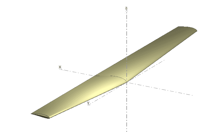
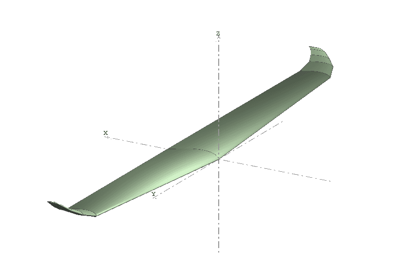
XFLR5 vortex lattice analysis was used to evaluate the aerodynamic effects of each configuration. Wing geometry was iterated to improve lift-to-drag performance and endurance while maintaining similar lift and stability characteristics.
CAD & Structural Layout
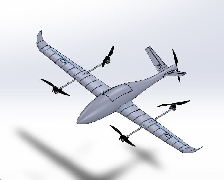
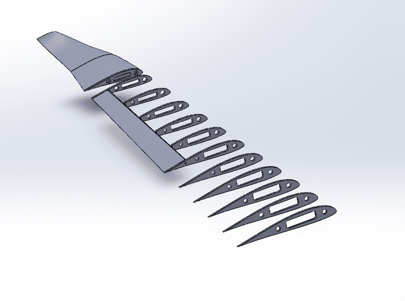
The complete airframe was modeled in SolidWorks around a carbon-fiber spar, with four dedicated lift rotors and a separate cruise motor for VTOL and fixed-wing flight.
The internal structure integrates the primary load paths with propulsion, avionics, and payload requirements, providing a foundation for subsequent structural validation and manufacturing.
Aerodynamic & Structural Analysis
ANSYS was used to evaluate aerodynamic loading, structural stresses, and safety margins. The resulting load cases determined the required specifications for the carbon-fiber spar, propulsion system, and other structural components.
Stack
- Python
- PySide6
- Matplotlib
- NumPy
- XFLR5
- SolidWorks
- Ansys Fluent
- ArduPilot